Silicon Carbide Thermal Conductivity
Silicon carbide (SiC) ceramics are widely used in high-tech industries such as electronics, aerospace, automobiles and semiconductors due to their excellent thermal conductivity, high strength and chemical corrosion resistance. Among them, thermal conductivity is a key parameter to measure the performance of silicon carbide ceramics, which directly affects its application performance in heat dissipation, thermal shock resistance and high-temperature structural parts.
Silicon carbide ceramics manufactured by different processes have different thermal conductivity. This article will focus on analyzing the thermal conductivity and application differences of reaction sintered silicon carbide (SISIC) and pressureless sintered silicon carbide (SSiC).

Four key factors affecting the thermal conductivity of silicon carbide
Crystal structure purity
The theoretical thermal conductivity of high-purity α-SiC single crystal can reach 490 W/(m·K), but the actual material is significantly reduced due to factors such as grain boundaries and impurities. For example, for every 0.1% increase in impurity content, the thermal conductivity decreases by about 5-8%.
Porosity
Porosity will hinder phonon transmission, and for every 1% increase in porosity, the thermal conductivity decreases by 5-10%. The porosity of SISIC is usually <0.5%, while the porosity of SSIC may reach 2% due to differences in sintering processes.
Sintering aids
The Al₂O₃-Y₂O₃ additive commonly used in SSIC will form a low thermal conductivity grain boundary phase (thermal conductivity <10 W/(m·K)), while the grain boundary thermal conductivity of SISIC can reach 120-150 W/(m·K) due to the presence of free silicon.
Grain size
Large grains (>20μm) can reduce the number of grain boundaries and increase thermal conductivity by 15-20%. SISIC grains are usually 1-5μm, and SSIC can reach 5-20μm.
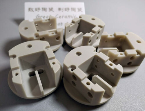
Reaction Bonded Silicon Carbide (SISIC)
Physical mechanism of temperature dependence of thermal conductivity
The heat conduction of silicon carbide lattice is mainly achieved through phonon transfer. Temperature changes will affect thermal conductivity in three aspects:
- Enhanced phonon scattering
Temperature increase intensifies lattice vibration (phonon concentration ↑), resulting in an increase in the probability of phonon-phonon scattering and a shortening of the mean free path (heat conduction resistance ↑) - Phase change and interface effect
The free silicon (melting point 1414℃) in RB-SiC softens when it approaches the melting point, causing a sharp increase in the thermal resistance of the silicon/SiC interface - Defect activation
At high temperatures, the diffusion of impurity atoms at the grain boundaries is intensified, forming additional scattering centers (especially above 500℃)
Typical temperature curve of SISIC thermal conductivity
Room temperature to 800℃ range (non-destructive temperature range)
- Thermal conductivity change: 180 W/(m·K) → 95 W/(m·K) (47% decrease)
- Dominant factor: Umklapp scattering dominates
- Key phenomenon:
- An inflection point appears at 300℃, and the thermal conductivity decrease rate slows down from -0.25 W/(m·K·℃) to -0.15 W/(m·K·℃)
- Grain boundary thermal resistance ratio increases from 15% to 35%
800-1300℃ range (structural stability limit)
- Thermal conductivity change: 95 W/(m·K) → 62 W/(m·K) (35% decrease)
- Dominant factors:
- The difference between the thermal expansion coefficient of free silicon (4.5×10⁻⁶/℃) and SiC (4.0×10⁻⁶/℃) leads to microcracks
- The viscous flow of silicon phase begins (>1200℃)
- Abnormal phenomenon:
- A local increase in thermal conductivity (about +5%) may occur around 1050℃, which is related to the improvement of silicon phase crystallinity
1300-1400℃ range (critical failure zone)
- Thermal conductivity change: 62 W/(m·K) → 28 W/(m·K) (55% decrease)
- Failure mechanism:
- Silicon phase melts to form a liquid film (>1414℃ completely melted)
- Porosity increases to 3-5%
Atmospheric Pressure Sintered Silicon Carbide (SSIC)
Physical mechanism of temperature dependence of thermal conductivity
1. Thermal conduction dominated by phonon scattering
The thermal conduction of PLS-SiC is mainly achieved through **lattice vibration (phonon)** transmission. Temperature changes affect thermal conductivity through the following channels:
- Umklapp scattering enhancement: The increase in temperature leads to an increase in phonon density, an intensified lattice anharmonic vibration, and a shortened mean free path.
- Grain boundary scattering effect: The grain boundary phase formed by sintering aids (such as Al₂O₃-Y₂O₃) has a low thermal conductivity (<10 W/(m·K)), and the proportion of grain boundary thermal resistance increases at high temperatures.
- Defect thermal activation: Above 500℃, the diffusion of lattice vacancies and impurity atoms intensifies, forming additional scattering centers.
2. Dynamic evolution of grain boundary phase
Low temperature zone (<600℃): The grain boundary glass phase remains solid, and the decrease in thermal conductivity is mainly dominated by phonon scattering.
- Medium and high temperature zone (600-1400℃): some grain boundary phases soften (such as Y-Si-Al-O glass phase), and the interfacial thermal resistance increases significantly.
- Ultra-high temperature zone (>1400℃): the grain boundary phase may decompose or volatilize, resulting in increased porosity.
Temperature characteristics of thermal conductivity
1. Room temperature to 600℃: linear decline stage
- Thermal conductivity change: 150 W/(m·K) → 110 W/(m·K) (decline of 27%)
- Dominant factor: Umklapp scattering dominates
- Key data:
- Thermal conductivity temperature coefficient: -0.07 W/(m·K·℃)
- Grain boundary thermal resistance ratio increased from 20% to 35%
2. 600-1400℃: nonlinear attenuation stage
- Thermal conductivity change: 110 W/(m·K) → 65 W/(m·K) (decline of 41%)
- Mechanism analysis:
- The viscosity of the glass phase at the grain boundary decreases, and the interface thermal resistance jumps (contribution rate > 50%)
- Microcracks germinate along the grain boundary (caused by differences in thermal expansion coefficients)
- Abnormal phenomenon:
- A short-term platform (change rate < 5%) may appear in the 800-1000℃ range, which is related to the partial crystallization of the grain boundary phase.
3. 1400-1600℃: Ultra-high temperature limit area
- Thermal conductivity change: 65 W/(m·K) → 45 W/(m·K) (31% decrease)
- Failure mechanism:
- Grain boundary phase volatilization (such as Y₂O₃ sublimation temperature> 2400℃, but local enriched areas may decompose)
- Abnormal grain growth (size increases from 5μm to 15μm), grain boundary density decreases but single crystal anisotropy increases
Comparative analysis of thermal conductivity-temperature curve
Comparison of typical temperature node data (unit: W/(m·K))
| Temperature(℃) | SISIC Thermal Conductivity | SSIC Thermal Conductivity | Performance Difference Rate |
|---|---|---|---|
| 25 | 175±8 | 165±7 | SISIC is better than 6% |
| 300 | 122±5 | 145±6 | SSIC is better than 19% |
| 600 | 89±4 | 110±5 | SSIC is better than 24% |
| 1000 | 58±3 | 85±4 | SSIC is better than 47% |
| 1400 | 32±2 | 65±3 | SSIC is better than 103% |
* The above data is for reference only.
Key turning points:
- 300℃: SSIC thermal conductivity completes grain boundary phase stabilization and surpasses RB-SiC
- 1000℃: SISIC silicon phase begins to flow, and the thermal conductivity decay rate increases to 0.2 W/(m·K·℃)
Engineering Selection Decision Matrix
Temperature-Scene Adaptation Guide
| Temperature range | Recommended Materials | Typical application scenarios |
|---|---|---|
| <500℃ | SISIC | Heat dissipation substrate, mechanical sealing ring |
| 500-1000℃ | SSIC | Gas turbine blade coatings, high temperature sensor housings |
| 1000-1400℃ | Modified SSIC | Rocket engine nozzles, nuclear reactor control rods |
| >1400℃ | CVI-SiC composites | Hypersonic vehicle nose cone, nuclear fusion first wall |
* The above data is for reference only.
Cost-performance balance strategy
- Limited budget + < 800℃: Choose SISIC (30-50% lower cost)
- Long-term high-temperature service: SSIC is preferred (lifespan extended by 2-3 times)
- Extreme thermal shock environment: SISIC (thermal shock resistance ΔT up to 800℃)
Industry measured data reference
Comparison of typical working conditions in the aviation field
| Parameter | SISIC (JAXA standard) | SSIC (NASA standard) |
|---|---|---|
| Mach 5 aerodynamic heating | Failure (1200℃) | Stable (surface 1450℃) |
| Thermal conductivity retention* | 38% | 72% |
| Thermal cycle times (ΔT=1000℃) | 50 Times | 200 Times |
* The above data is for reference only.
Based on the thermal conductivity at 25°C, this is the retention rate after 30 minutes of high temperature exposure
Long-term performance of energy equipment
| Material Type | Thermal cracking reactor lining (850℃/5000h) | Nuclear waste container (400℃/10 years) |
|---|---|---|
| SISIC | Thermal conductivity decreased by 23%, and cracks appeared | Stable performance, attenuation <3% |
| SSIC | Thermal conductivity attenuation 9%, complete structure | Grain boundary phase precipitation, attenuation 8% |
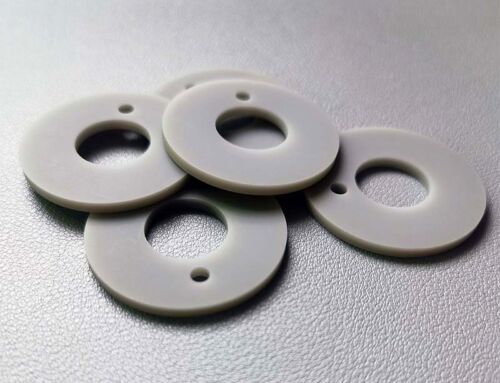
Pressureless Sintered Silicon Carbide (SSiC)
Reaction sintered and pressureless sintered silicon carbide each have their own advantages in thermal conductivity. Engineering selection needs to comprehensively consider temperature, medium environment and cost to achieve the best thermal management solution. If you are still not sure which material is suitable for your application, please contact us.